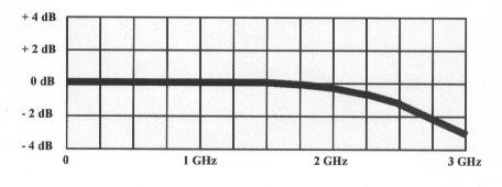
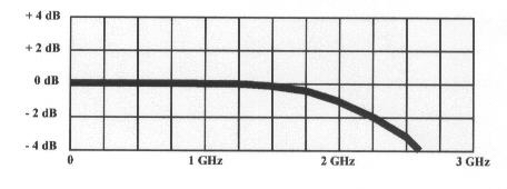
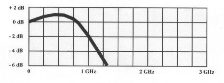
Typical P-20A RF probe response
|
|
|
Product Information Page |
|
Typical P-20A RF probe response |
|
![]()
|
DESCRIPTION |
|
|
![]()
|
THEORY OF OPERATION |
|
|
![]()
|
RF GROUNDING |
|
|
![]()
|
TYPICAL P-20A RF PROBE RESPONSE |
![]()
|
RF VOLTAGE MEASUREMENTS |
|
|
![]()
|
RF POWER MEASUREMENTS |
|
|
![]()
CORRECTION FACTOR FOR LOADING EFFECTS
|
CORRECTION FACTOR FOR LOADING EFFECTS |
|||||||||||||||||||||||||||
|
|
|||||||||||||||||||||||||||
![]()
|
POWER LEVEL CONVERSION |
|||||||||||||||||||||||||||||||
|
![]()
|
RF SIGNAL INJECTION |
|
|
![]()
|
PERFORMANCE VERIFICATION |
|
|
![]()
|
CROSS REFERENCE LEVEL CHART |
|||||||||||||||||||||||||||||||||||||||||||||||||||||||||||||||||||||||||||||||||||||||||||||||||||||||||||||||||||||||||||||||||||||||||||||||||||||||||||||||||||||||||||||||||||||||||||||||||||||||||||||||||||||||||||||||||||||||||||||||||||||||||||||||||||||||||||||||||||||
|
![]()
|
SPECIFICATIONS |
||
|
![]()
|
LIMITED WARRANTY |
|
|
![]()
Last modified: 05-21-2010